
PRECISION FINISHING / BUILD TO PRINT
Centerless Grinding Services
Consistent diameters. Controlled roundness. Repeatable batches.
Precision centerless grinding for suitable shafts, pins, bars, rollers, and cylindrical blanks. We coordinate incoming stock, machining, heat treatment, grinding, and inspection for drawing-defined diameter, roundness, straightness, and surface finish.
- Through-feed grinding and reviewed in-feed options
- Prototype and repeat small-batch production
- Machining, grinding, and inspection in one project
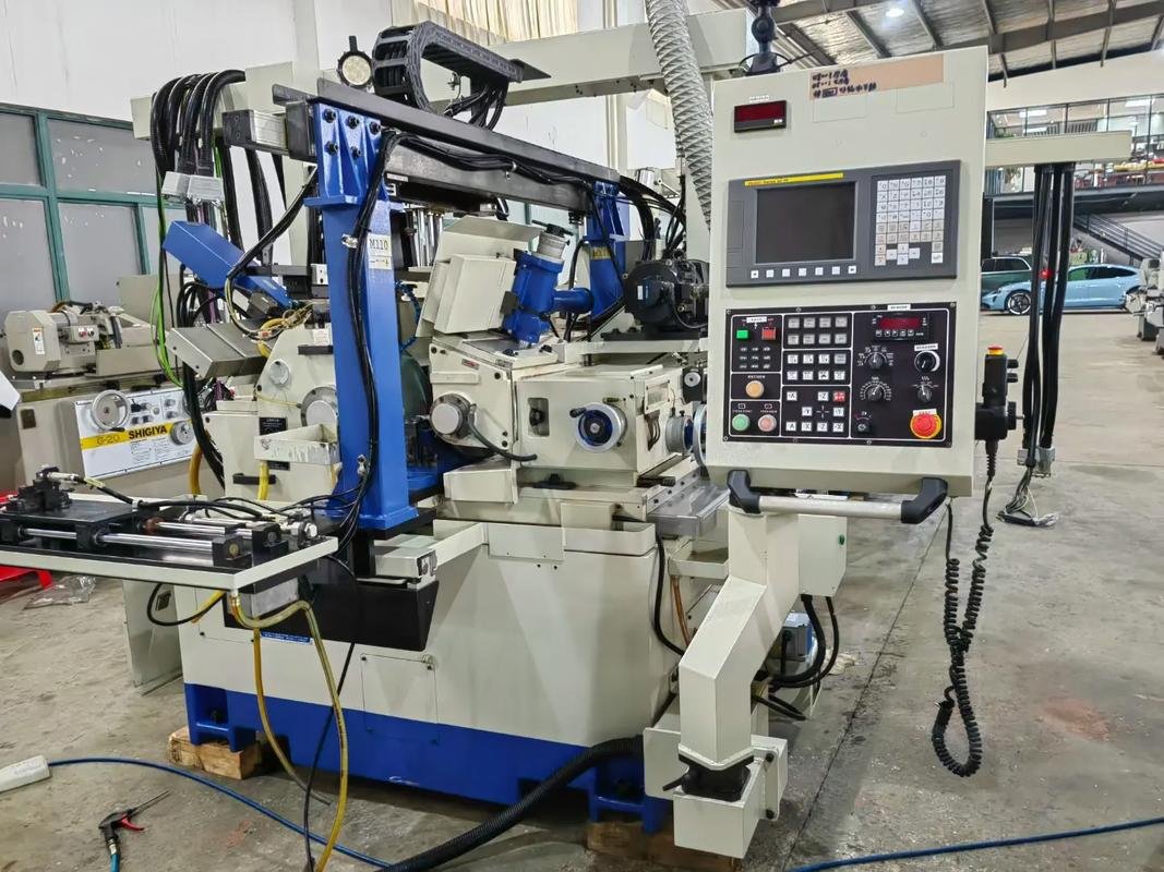
Centerless Grinding Capabilities & Specifications
Our centerless grinding capabilities support precision shafts, pins, rods, dowels, rollers, bushings, and other cylindrical components requiring consistent diameter, roundness, straightness, and surface finish. Through-feed and in-feed grinding can support both repeat production and precision small-batch requirements.
±0.002 mm*
Precision Diameter Tolerance
0.002 mm*
Roundness
Ra 0.1 μm*
Best Surface Finish
Ø1–100 mm*
Grinding Diameter Range
Technical Specifications
Processes & Production
- Grinding Processes
- Through-Feed Centerless Grinding, In-Feed / Plunge Centerless Grinding*
- Production Method
- Through-feed for continuous cylindrical parts; in-feed for shoulders, steps, and defined grinding zones*
- Production Volume
- Prototypes, small batches, and repeat production
Size & Dimensional Control
- Diameter Range
- Ø1–100 mm (0.039–3.94 in)*
- Typical Diameter Tolerance
- ±0.005 mm (±0.0002 in)
- Precision Diameter Tolerance
- Down to ±0.002 mm (±0.00008 in)*
- Roundness
- Down to 0.002 mm (0.00008 in)*
- Straightness
- Down to 0.003 mm per 300 mm*
Surface & Material Condition
- Typical Surface Finish
- Ra 0.2–0.8 μm
- Best Surface Finish
- Down to Ra 0.1 μm*
- Material Hardness
- Soft and hardened materials; up to approximately 65 HRC for suitable steels*
*Maximum diameter range and maximum precision represent separate capability limits and may not be achievable simultaneously. Final capability depends on diameter, length-to-diameter ratio, geometry, material, hardness, stock allowance, grinding method, wheel selection, setup, and inspection method.
Where Centerless Grinding Adds Precision
Centerless grinding can finish suitable cylindrical parts without center holes or chucking at the ground diameter. The manufacturing plan connects outside-diameter control with stock straightness, roundness, surface condition, and batch consistency.
Mating Diameters
Controlled outside sizes for locating, sliding, or press-fit interfaces.
Consistent Round Sections
Roundness control for functional cylindrical surfaces and repeat assembly.
Precision Stock Preparation
Consistent round blanks before subsequent machining, coating, or assembly.
Repeat Batch Consistency
Planned gauging and handling to monitor size trends and surface condition.
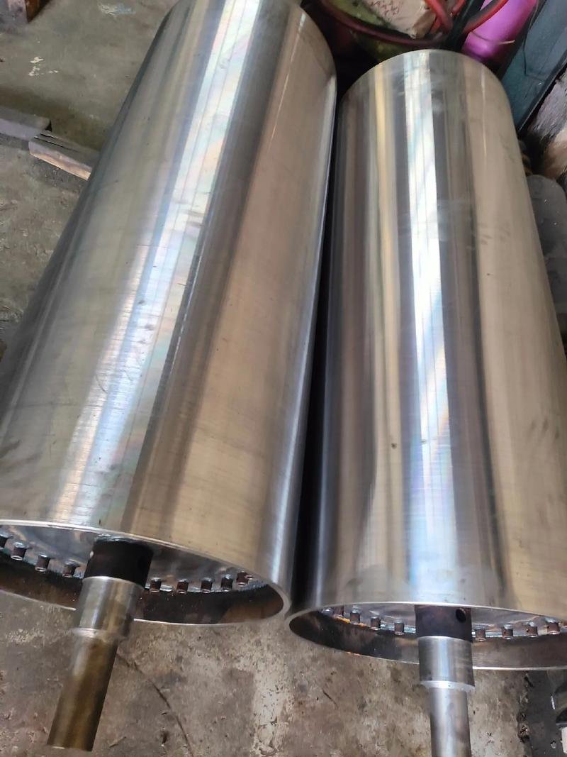
Centerless Grinding Processes We Support
Through-feed grinding generally requires a continuous geometry that can travel through the grinding zone. Shoulders, heads, multiple diameters, interrupted features, and certain short or thin-wall components may require in-feed grinding, another method, or a different manufacturing route. Datum-related runout must be assessed separately.
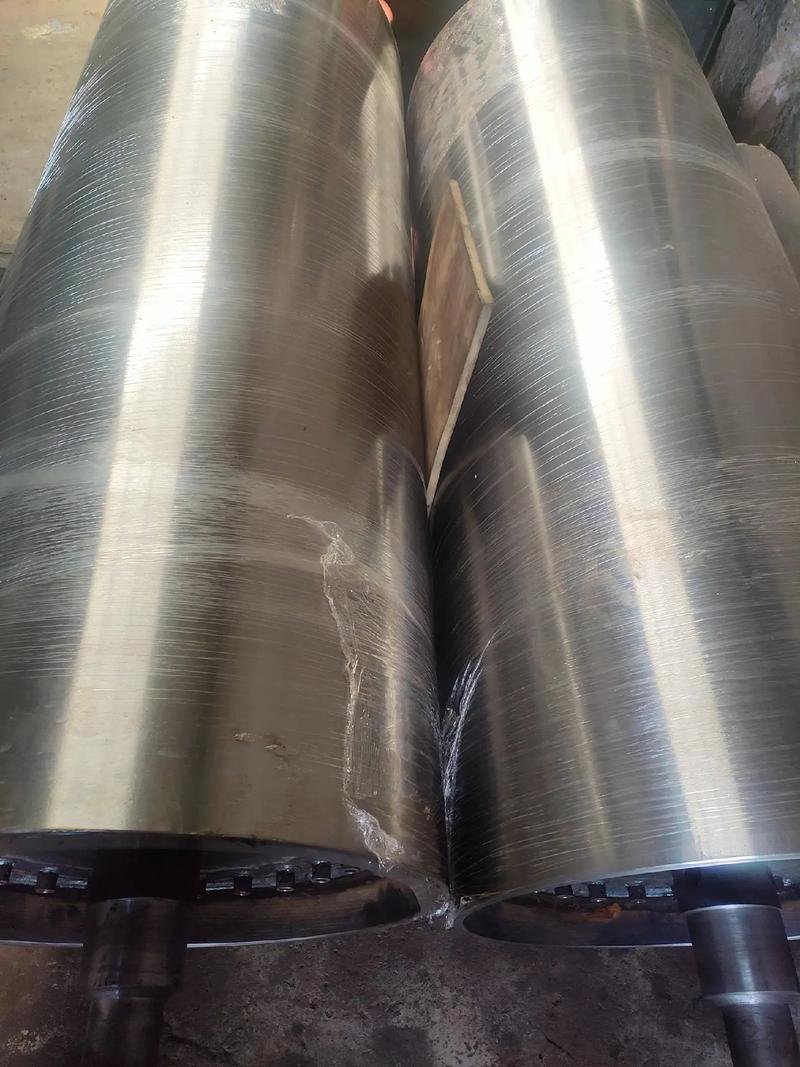
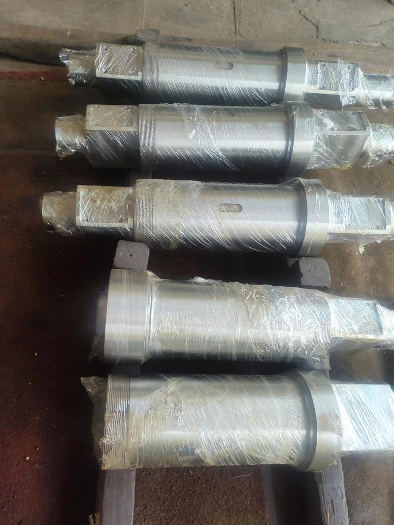
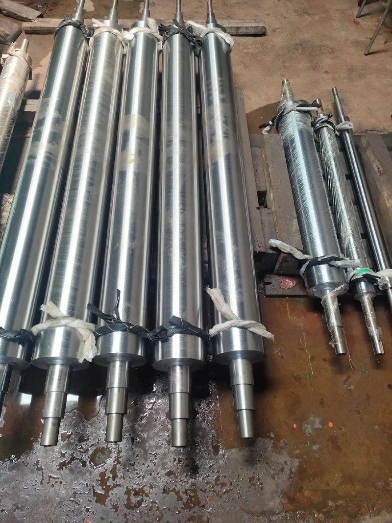
Parts We Grind
- Precision shafts
- Pins
- Dowel pins
- Rods
- Rollers
- Bushings
- Axles
- Valve components
- Bearing components
- Guide pins
- Tooling components
- Precision cylindrical blanks
Shoulders, flats, cross holes, wall thickness, and end features affect process selection. A cylindrical part is not automatically suitable for through-feed grinding.
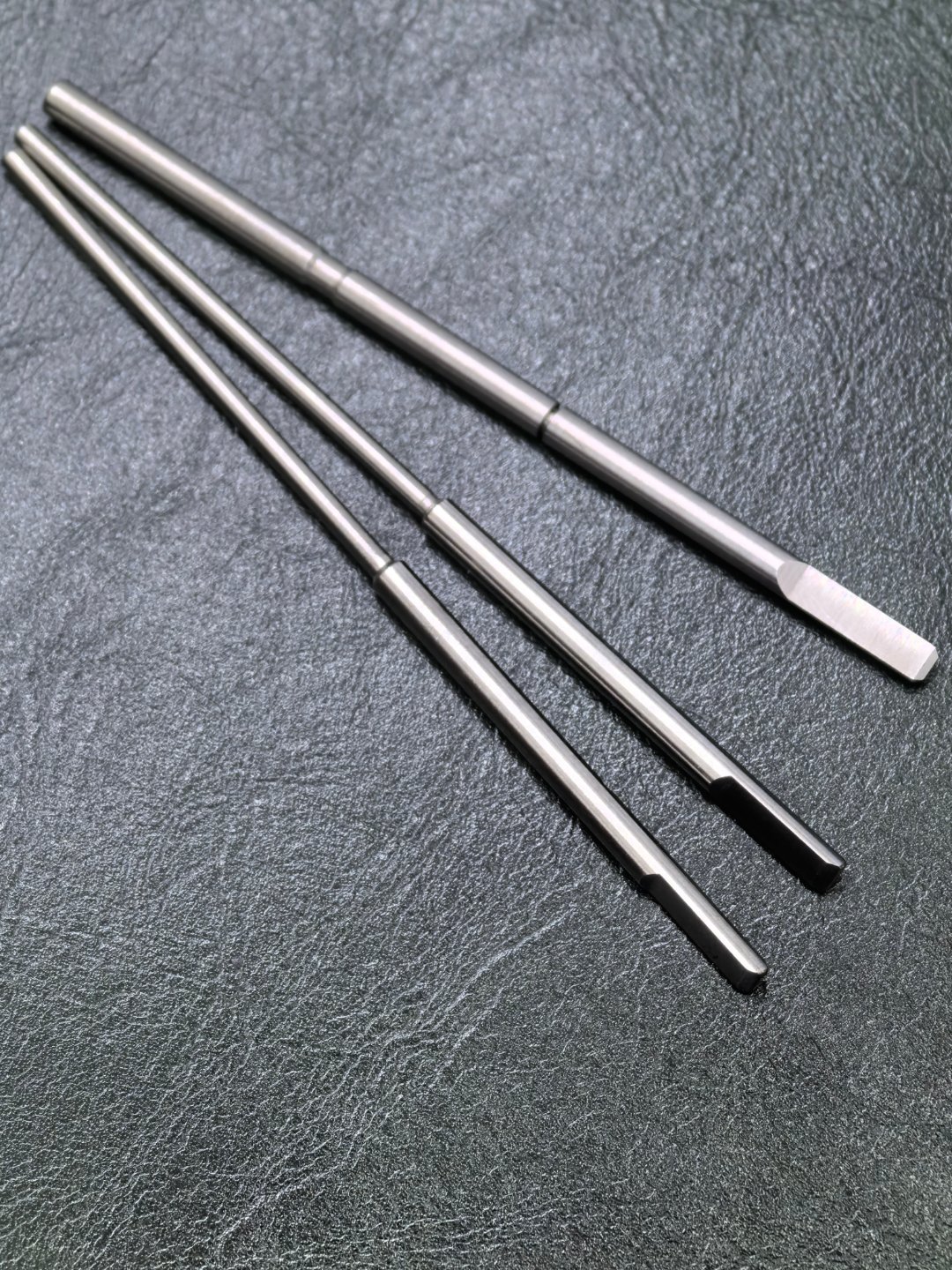
From Drawing Review to Final Grinding
- Drawing & Part Suitability Review
Check diameters, profile, length, datums, roundness, straightness, finish, material, hardness, and quantity; select through-feed or infeed. - Pre-Machining & Incoming Stock
Prepare blanks or turned features with controlled stock. Check starting diameter, straightness, and the available entry and exit support. - Heat Treatment & Stock Condition
Coordinate hardening or other treatment when specified. Review movement, remaining allowance, and surface condition before the grinding setup. - Setup, Trial & Centerless Grinding
Set the blade and wheels, dress as required, and verify early pieces. Monitor coolant, feed or plunge cycle, wheel condition, size trend, and handling throughout the run. - Final Inspection
Verify the specified outside diameters, roundness, straightness, cylindricity where required, surface finish, and agreed documentation.
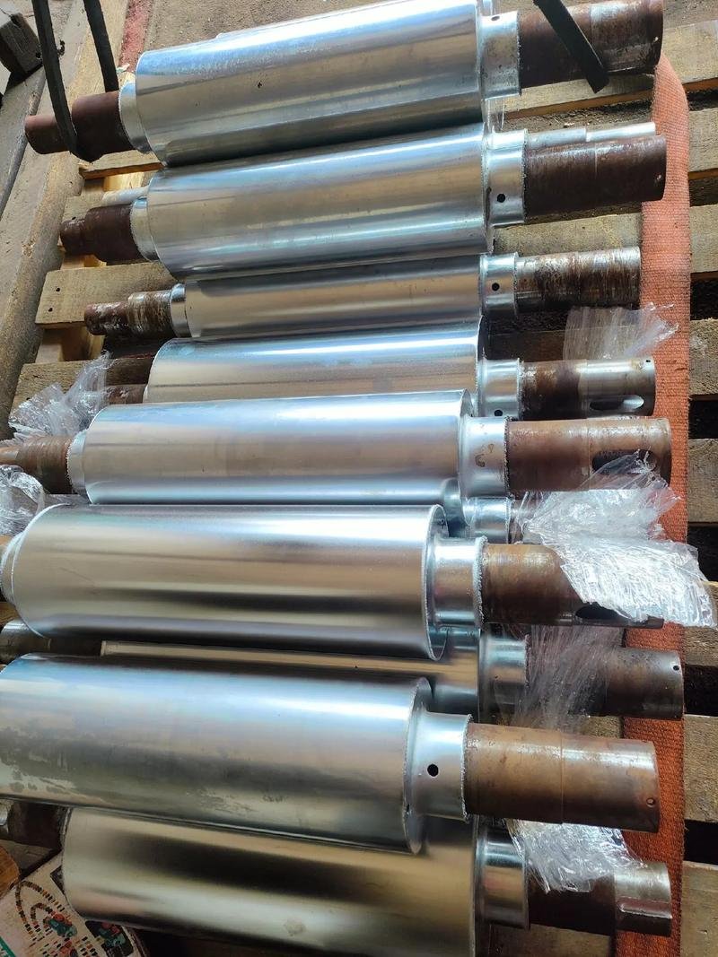
Materials for Centerless Grinding
Carbon & Alloy Steels
1018, 1045, C45, 4140, 4340, and similar grades.
Hardened Steels
Bearing steels, hardened alloy steels, and other heat-treated components.
Stainless Steels
304, 316, 416, 420, 17-4PH.
Tool Steels
H13, O1, A2, D2, S7.
Non-Ferrous & Special Alloys
Selected aluminum, copper alloys, titanium, Inconel, and other grindable materials depending on geometry and requirements.
Material grade, hardness, stock allowance, geometry, and required surface finish are reviewed together when selecting the grinding approach.
Controlling Diameter, Roundness & Straightness
A diameter reading alone does not establish roundness, straightness, or runout to another feature. Incoming stock, wheel and blade geometry, work support, feed conditions, and the inspection datum determine which requirements the route can control.
- Outside diameter
- Diameter consistency
- Roundness
- Straightness
- Cylindricity
- Surface finish
- Taper control
- Lot-to-lot dimensional consistency
Roundness & Wheel Setup
Set work height, blade condition, wheel geometry, and regulating conditions around stable roundness.
Straightness & Support
Review incoming stock, part length, slenderness, feeding, and exit support for shaft consistency.
Diameter Trend
Use appropriate in-process checks and final gauges to manage size drift through the batch.
Surface & Datum Relationships
Control dressing, coolant, feed, and handling for surface condition. Runout or concentricity to other features requires a defined datum and measurement plan.
Cylindricity & Taper
Evaluate form along the working length, not only one diameter section. Track lot-to-lot dimensional consistency against the agreed sampling plan.
Inspection & Quality Documentation
Requirement & Typical Inspection Method
- Outside Diameter
- Micrometer / dimensional gauge
- Roundness
- Roundness tester
- Straightness
- Precision indicator / CMM / suitable straightness measurement
- Cylindricity
- Form measurement / CMM
- Surface Finish
- Surface roughness tester
- Production Consistency
- In-process gauging / sampling inspection / SPC where required
A micrometer size check does not establish roundness. Roundness and datum-related runout require separate methods; inspection setup and resolution must suit the feature and tolerance.
Typical Inspection Equipment
- Digital micrometers
- Comparative gauges as required
- Roundness / form measurement
- CMM where appropriate
- Surface roughness tester
- Indicators and specified datum fixtures
Quality Documentation
- FAI (first article inspection), when specified
- COC (certificate of conformity), when agreed
- Dimensional inspection reports
- Material certificates
- Custom inspection documentation upon request
Inspection methods and required records are agreed with the quotation, using equipment and measurement resolution suited to each feature and tolerance.
Centerless Grinding FAQ
What diameter tolerances and surface finishes can you hold?
Typical diameter tolerance is ±0.005 mm (±0.0002 in), with a proposed precision limit of ±0.002 mm. Typical finish is Ra 0.2–0.8 μm, with a proposed best finish of Ra 0.1 μm. Starred precision limits
Should my part use through-feed or infeed grinding?
Through-feed suits continuous cylindrical profiles that can pass through the wheels. In-feed can suit selected headed, stepped, or formed parts at a controlled axial position; this capability.
Can you grind hardened parts after heat treatment?
Selected hardened steels and other suitable materials can be finish-ground. Hardness, distortion, straightness, stock allowance, and surface-integrity requirements are included in the process review.
Can you hold runout to a bore or another shaft feature?
That relationship must be specified and verified separately. Centerless support does not automatically establish a bore or center-hole datum. A cylindrical grinding or other referencing route may be more appropriate.
Can you machine and grind the complete part?
Yes. Stock preparation, turning, additional milling, heat treatment, grinding, finishing, and inspection can be coordinated as a build-to-print project.
How do you inspect roundness and straightness?
Use appropriate roundness or form measurement for roundness and a suitable CMM or form measurement plan for straightness. Part support, sampling, and instrument resolution follow the required tolerance.
Do you support prototypes and repeat small batches?
Yes. Include the initial quantity, repeat demand, and incoming stock condition so setup, handling, and the gauging plan can be matched to the order.
What should I include with a centerless grinding RFQ?
Send CAD and PDF drawings with finished diameter, overall length, profile and end features, material, hardness, incoming stock, quantity, roundness, straightness, surface finish, datum relationships, and required inspection records.
Send Us Your Grinding Drawing
Upload your CAD file and drawing with material, hardness, incoming stock, quantity, finished diameters, length, profile, roundness, straightness, surface finish, and inspection requirements. Our engineering team will review part suitability and the complete manufacturing route before quotation.