
Build-to-print gear components
CNC Gear
Manufacturing Services
Custom gear components made from your drawings for prototypes, replacement parts, and small-batch production. Discuss tooth geometry, material, heat treatment, and inspection requirements with 6CNC.
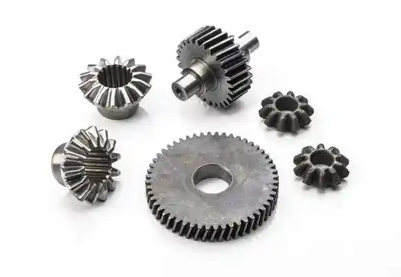
- Drawing-defined geometry
- Metal and engineering plastic options
- Prototype and small-batch projects
Gear types
Custom Gear Types
We review drawing-defined gears and toothed components. Manufacturing feasibility is confirmed against the geometry, material, accuracy, and inspection requirements.

Spur & helical gears
External tooth forms with drawing-defined pitch, pressure angle, and helix requirements.

Internal gears
Internal tooth profiles for compact drives and custom mechanical assemblies.
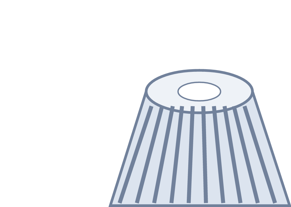
Bevel gears
Straight or selected custom bevel geometries, subject to drawing review.
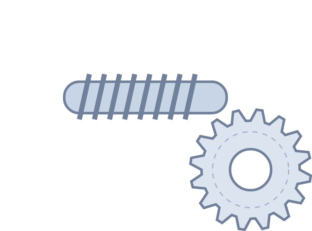
Worm gears & shafts
Drawing-defined components with mating requirements supplied for review.

Gear shafts & pinions
Teeth combined with journals, bearing seats, keyways, and other shaft features.

Racks & sectors
Linear racks and partial gear segments made to your specification.
Gear type illustrations — simplified, not production geometry.
Technical specifications
Gear Drawing Requirements
A CAD model alone may not capture every functional requirement. Include the tooth specification and critical relationships on your controlled drawing.
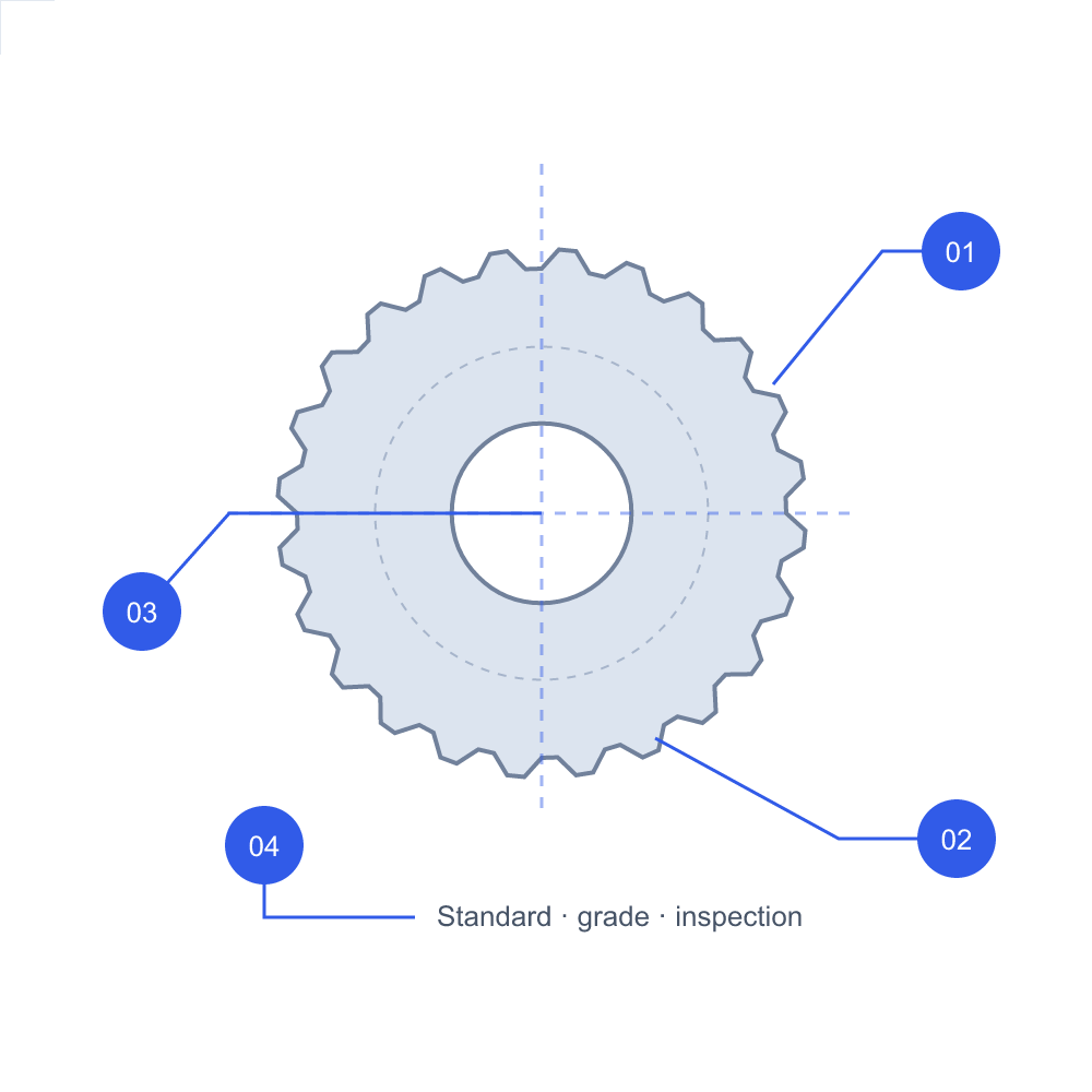
01
Gear tooth specifications
Tooth count, module or diametral pitch, pressure angle, and helix angle where applicable.
02
Gear assembly requirements
Mating-part information, backlash, center distance, and assembly requirements where specified.
03
Bores, journals and datums
Bores, journals, faces, runout, and other drawing-defined datum relationships.
04
Standards and inspection criteria
Applicable standard and grade, material condition, heat treatment, and inspection requirements.
Manufacturing process
Gear Manufacturing Process
Gear geometry, material, quantity, and inspection needs guide the process selection. Agree on the manufacturing scope before production begins.
01
Review & blank machining
Review the drawing, then plan turning and milling for bores, hubs, faces, and reference features.
02
Tooth cutting
Consider hobbing, shaping, CNC milling, or selected EDM routes according to geometry and access.
03
Treatment & finishing
Coordinate specified heat treatment and finishing with the requirements for final fits and surfaces.
04
Inspection & delivery
Check the agreed dimensions and gear features against the controlled drawing and inspection plan.
Materials and finishing
Gear Materials and Heat Treatment
Specify the material grade and final condition together. Treatment and finishing requirements must be considered alongside critical dimensions.
| Material group | Grades and options |
|---|---|
| Carbon & alloy steels | 1045, 4140, 4340 and drawing-specified grades. |
| Stainless steels | 303, 304, 316 and 17-4 PH. |
| Tool & bearing steels | Selected grades, subject to hardness and process review. |
| Aluminum | 6061, 7075 and specified alloys. |
| Brass & bronze | Drawing-specified brass and bronze grades. |
| Engineering plastics | POM, PEEK, nylon and selected polymers. |
Heat treatment and surface finishingInclude required hardness, case depth, coating thickness, masking, and post-treatment dimensional requirements where applicable.
Quality requirements
Gear Inspection and Quality Control
State the required standard, grade, and acceptance criteria. The inspection scope and supporting records are agreed against the drawing and quotation.
Gear tooth inspection
Identify the tooth features and inspection requirements that need verification.
Runout and concentricity
Define runout, bore alignment, journal relationships, and mounting references.
Material and heat-treatment records
Specify certification, hardness, heat-treatment, and finish documentation needs.
First-article inspection reports
Agree on first-article checks and reporting before the batch proceeds.
Prototypes and replacement parts
Prototype and Small-Batch Gears
Prototype projects
Provide the current drawing revision and the features your testing needs to evaluate.
Replacement components
Send the controlled drawing or available specification and mating-part information for feasibility review.
Repeat batches
Identify approved revisions, material requirements, and inspection records for the next order.
Quantity, tooling, treatment, and inspection requirements influence the proposed route and quotation.
Common questions
CNC Gear Manufacturing FAQ
Can you review a gear without a CAD model?
A controlled drawing or complete specification is preferred. Send available photos, measurements, and mating-part information so feasibility can be reviewed.
Can you machine hardened gears?
Selected materials can be reviewed. The route depends on hardness, tooth geometry, accuracy, and finishing requirements.
Can you manufacture a mating gear set?
Submit the full set specification, shaft arrangement, center distance, and backlash requirements for review.
What determines the lead time?
Geometry, material availability, quantity, tooling, treatment, finishing, and inspection affect the schedule. Include your required delivery date with the inquiry.
Gear quotation
Request a Custom Gear Quote
Send your drawing and project requirements to discuss a suitable machining route and request a quotation.