
PRECISION FINISHING / BUILD TO PRINT
Cylindrical Grinding Services
Controlled diameters. Reliable fits. Functional surfaces.
Precision cylindrical grinding for shafts, journals, bearing seats, sleeves, pins, rollers, and other rotational parts. From prototypes to production, 6CNC coordinate turning, heat treatment, grinding, and inspection for critical diameters, fits, runout, and surface finish.
- Prototype and low-volume production
- Turning, grinding, and inspection in one project
- Tight diameter, roundness, and runout control
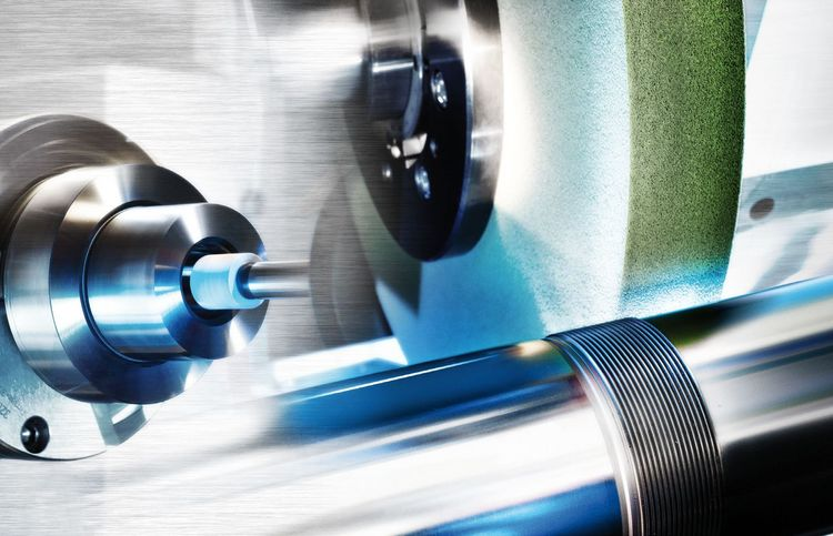
Cylindrical Grinding Capabilities & Specifications
6CNC cylindrical grinding capabilities support precision shafts, journals, bearing seats, sleeves, pins, rollers, and other rotational parts. Grinding can be integrated with CNC turning, heat treatment, surface finishing, and inspection for complete build-to-print production.
±0.002mm*
Precision Diameter Tolerance
Ra 0.1μm*
Best Surface Finish
Ø500mm*
Maximum Grinding Diameter
2,000mm*
Maximum Grinding Length
Technical Specifications
Types, Methods & Workholding
- Grinding Types
- OD Grinding, ID Grinding*
- Grinding Methods
- Traverse Grinding, Plunge Grinding
- Workholding
- Between Centers, Chucking
Capacity & Production
- Maximum Grinding Diameter
- Up to 500 mm (19.7 in)*
- Maximum Grinding Length
- Up to 2,000 mm (78.7 in)*
- Maximum Part Weight
- Up to 500 kg (1,102 lb)*
- Diameter Range
- Ø3–500 mm*
- Production Volume
- Prototypes, low-volume, and repeat production
Precision & Material Condition
- Typical Diameter Tolerance
- ±0.005 mm (±0.0002 in)
- Precision Diameter Tolerance
- Down to ±0.002 mm (±0.00008 in)*
- Roundness
- Down to 0.002 mm (0.00008 in)*
- Cylindricity
- Down to 0.003 mm (0.00012 in)*
- Runout
- Down to 0.003 mm (0.00012 in)*
- Typical Surface Finish
- Ra 0.2–0.8 μm
- Best Surface Finish
- Down to Ra 0.1 μm*
- Hardened Materials
- Up to approximately 65 HRC for suitable steels*
*Maximum size and maximum precision represent separate capability limits and may not be achievable simultaneously. Final capability depends on workpiece diameter, length, geometry, material, hardness, wall thickness, grinding setup, datum scheme, and inspection method. Drawing review is required for critical tolerances.
Where Cylindrical Grinding Adds Precision
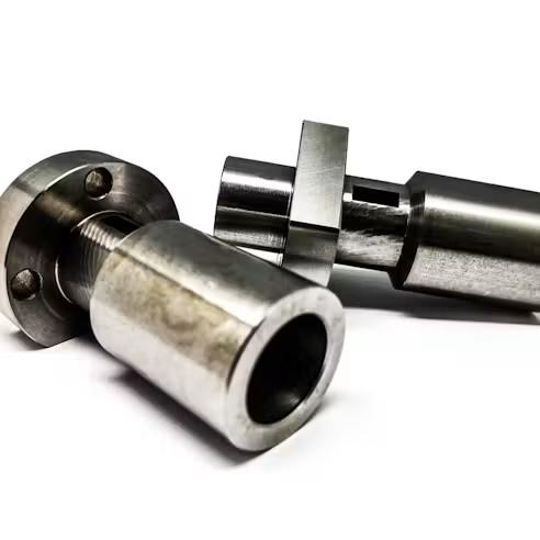
Turning establishes the overall geometry. Cylindrical grinding is used where selected diameters and functional surfaces require tighter size control, better roundness, lower runout, improved surface finish, or final sizing after heat treatment.
6CNC review each ground feature as part of the assembly: which datum controls it, how it is supported, what remains after heat treatment, and how the result will be measured.
- Bearing fits — controlled bearing journals and seats for accurate interfaces.
- Seal contact surfaces — fine running surfaces with specified diameter and finish.
- Precision locating diameters and press-fit mating surfaces.
- Concentric stepped diameters for rotating assemblies and spindle features.
- Hardened shaft surfaces restored to final size after heat treatment.
Cylindrical Grinding Processes 6CNC Support
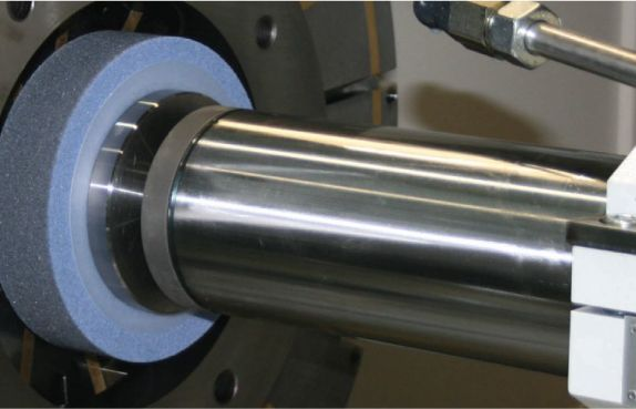
Grinding Types
OD Grinding
Finish outside diameters on shafts, sleeves, pins, and rollers. Traverse or plunge passes are selected around feature length, shoulders, reliefs, and wheel access.
ID Grinding*
Internal cylindrical grinding for specified bores.
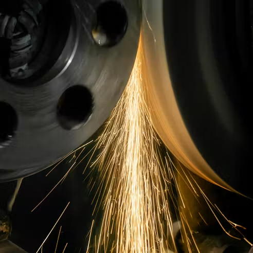
Grinding Methods
Traverse Grinding
Longitudinal passes finish extended cylindrical surfaces with controlled overlap and stock removal.
Plunge Grinding
Radial infeed finishes shorter journals or shoulders where wheel width, reliefs, and access suit the feature.
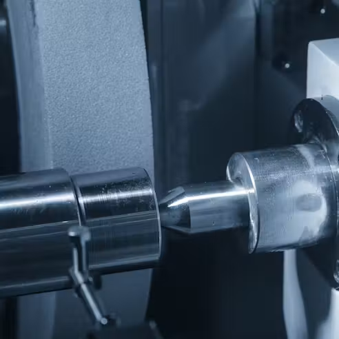
Workholding
Between Centers
Where the drawing and center condition allow, center references help relate multiple diameters to a common axis. Long or slender parts require suitable support and a clear runout inspection plan.
Chucking
Chuck or fixture location supports parts with suitable gripping features; alignment follows the functional datum scheme.
Wheel condition, coolant, and pass strategy are planned around the material, hardness, grinding allowance, and required surface integrity.
Parts Grind
- Shafts
- Journals
- Spindles
- Axles
- Pins
- Rollers
- Sleeves
- Bushings
- Bearing seats
- Tooling components
- Rotational precision components
From Drawing Review to Final Grinding
- Drawing & Datum Review
Review critical diameters, tolerances, GD&T, runout, material, hardness, surface finish, and inspection requirements. - Pre-Machining
Turning and milling establish the required geometry while maintaining controlled grinding stock, centers, and chucking features. - Heat Treatment
Hardening, stress relief, or other treatment is coordinated when required by the drawing. Account for distortion and remaining grinding allowance. - Cylindrical Grinding
Align and support the workpiece; select and dress the wheel for the material and contact area. Finish-grind critical journals, diameters, and bearing seats using the appropriate method, including controlled spark-out. - Final Inspection
Diameter, roundness, cylindricity, runout, straightness, and surface finish are verified according to the approved drawing.
Materials for Cylindrical Grinding
Hardened Steels
4140, 4340, bearing steels, tool steels such as A2 and D2, and other hardened components. Carbon steel such as 1045 can also be specified.
Stainless Steels
303, 304, 316, 17-4PH, and other machinable stainless grades.
Non-Ferrous Metals
Aluminum, copper alloys including brass and bronze, and selected titanium alloys.
High-Temperature Alloys
Selected nickel-based alloys including Inconel.
Material grade, hardness, stock allowance, part geometry, and required surface finish are reviewed together when selecting the grinding approach.
DRAWING-BASED QUALITY
Controlling Diameter, Roundness & Runout
A correct diameter is only one part of a precision grinding requirement. Functional performance can also depend on roundness, cylindricity, taper, straightness, concentricity, runout, datum relationships, and surface finish.
Diameter & form
Specify the size tolerance together with any roundness, cylindricity, taper, or straightness requirements.
Datums & runout
Identify the functional axis and references for circular or total runout. Setup and measurement must use the agreed datum system.
Surface & condition
Define roughness, measurement direction, hardness, and any surface-integrity requirements for bearing, sealing, or sliding contact.
Inspection & Quality Documentation
- Diameter
- Micrometer / CMM
- Roundness
- Roundness tester
- Cylindricity
- CMM / form measurement
- Runout
- Indicator / CMM
- Surface Finish
- Surface roughness tester
- Length / Position
- CMM / height measurement
Inspection methods are selected according to the feature and tolerance being controlled rather than relying on a single measurement system.
Typical Inspection Equipment
- CMM
- Roundness tester
- Surface roughness tester
- Digital micrometers
- Bore gauges
- Height gauges
- Gauge blocks
- Calipers
Quality Documentation
- FAI
- COC
- Dimensional inspection reports
- Material certificates
- Custom inspection documentation upon request
Specify required records with the RFQ so the inspection and documentation scope is included in the quotation.
Cylindrical Grinding FAQ
What tolerances can you hold with cylindrical grinding?
Typical diameter tolerance is ±0.005 mm (±0.0002 in). The proposed precision limit of ±0.002 mm (±0.00008 in)*
What surface finish can cylindrical grinding achieve?
Typical surface finish is Ra 0.2–0.8 μm. The proposed best finish of Ra 0.1 μm*
Can you grind hardened steel parts?
Yes, suitable hardened steel features can be finish-ground. The proposed upper hardness of approximately 65 HRC*
Can you grind parts after heat treatment?
Yes. Pre-machining leaves controlled stock so selected features can be restored to final size after hardening or thermal processing. Distortion, datum condition, and surface integrity are considered in the manufacturing route.
Can you machine and grind the complete part?
Yes. Turning, milling, heat treatment, grinding, finishing, and inspection can be coordinated as a build-to-print project. The quoted scope defines the operations included.
How do you inspect roundness and runout?
Roundness is checked with a roundness tester. Runout is checked with an indicator or CMM against the specified datum axis. The selected method, setup, and measurement resolution must suit the drawing tolerance.
What information should I include with my RFQ?
Send a 3D CAD model and PDF drawing, material grade, hardness, heat-treatment condition, critical diameters, tolerances, GD&T, datums, surface finish, quantity, and required inspection documentation.
Do you support prototype and low-volume production?
Yes. We support prototypes, low-volume batches, and repeat production. Include your order quantity and expected repeat demand so the machining route and inspection scope can be planned.
START WITH YOUR DRAWING
Send Us Your Grinding Drawing
Upload your CAD file or drawing with material, hardness, critical diameters, tolerances, GD&T, surface finish, and quantity. Our engineering team will review the grinding requirements and manufacturing route before quotation.