
PRECISION FINISHING / BUILD TO PRINT
Surface Grinding Services
Controlled flatness. Parallel faces. Functional surfaces.
Precision surface grinding for plates, blocks, tooling, inserts, spacers, and other components with critical flat faces. We coordinate machining, heat treatment, grinding, and inspection around the thickness, flatness, parallelism, and surface finish specified on your drawing.
- Prototype and low-volume production
- Machining, heat treatment, and grinding in one project
- Flatness, parallelism, and thickness control
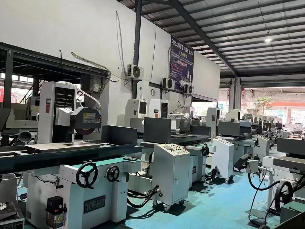
Surface Grinding Capabilities & Specifications
6CNC surface grinding capabilities support precision plates, blocks, tooling components, machine parts, and hardened components where flatness, parallelism, thickness control, and surface finish are critical. Surface grinding can be integrated with CNC machining, heat treatment, finishing, and inspection as part of a complete build-to-print manufacturing route.
±0.003 mm*
Precision Thickness Tolerance
0.003 mm*
Flatness
Ra 0.1 μm*
Best Surface Finish
1,000 × 500 mm*
Maximum Grinding Area
Technical Specifications
Processes & Workholding
- Grinding Processes
- Precision Surface Grinding, Peripheral Grinding, Face Grinding
- Workholding
- Magnetic Chuck, Mechanical Fixturing, Custom Fixturing
Capacity & Production
- Maximum Grinding Area
- Up to 1,000 × 500 mm (39.4 × 19.7 in)*
- Maximum Workpiece Height
- Up to 400 mm (15.7 in)*
- Maximum Part Weight
- Up to 500 kg (1,102 lb)*
- Production Volume
- Prototypes, 1–600 part small batches, and repeat production
Precision & Material Condition
- Typical Thickness Tolerance
- ±0.005 mm (±0.0002 in)
- Precision Thickness Tolerance
- Down to ±0.003 mm (±0.00012 in)*
- Flatness
- Down to 0.003 mm (0.00012 in)*
- Parallelism
- Down to 0.003 mm (0.00012 in)*
- Typical Surface Finish
- Ra 0.2–0.8 μm
- Best Surface Finish
- Down to Ra 0.1 μm*
- Material Hardness
- Soft and hardened materials; up to approximately 65 HRC for suitable steels*
*Maximum workpiece size and maximum precision represent separate capability limits and may not be achievable simultaneously. Final capability depends on part size, geometry, material, hardness, stock allowance, workholding, grinding direction, thermal stability, and inspection method. Critical requirements are confirmed during drawing review.
Where Surface Grinding Adds Precision
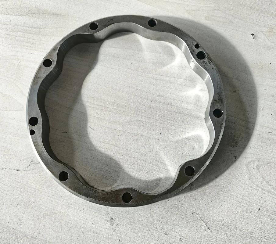
When a milled or heat-treated surface must become flatter, more parallel, or more consistent, surface grinding provides a controlled finishing route. The workpiece is supported on a suitable chuck or fixture while small amounts of stock are removed from the specified faces.
Datum & Reference Faces
Stable reference pads and locating faces for repeatable component positioning.
Parallel Mating Faces
Opposing surfaces with a defined relationship for assembly and load distribution.
Controlled Thickness
Finished sections for stack heights, clearances, and spacer dimensions.
Post-Heat-Treatment Finishing
Final sizing of selected hardened faces after thermal processing and distortion.
Guide & Mounting Surfaces
Reference surfaces, precision mating faces, and mounting interfaces with controlled geometry.
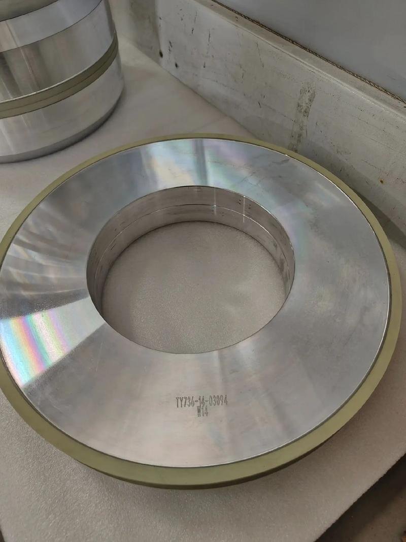
Surface Grinding Processes 6CNC Support
Wheel specification, dressing condition, feeds, and passes are selected for the material and contact area. Small and delicate parts require controlled support and handling.
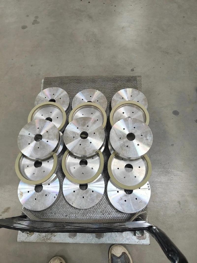
Parts We Grind
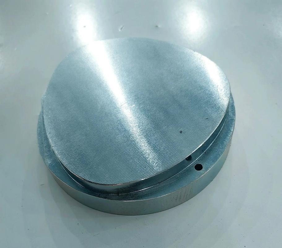
- Precision plates
- Machine blocks
- Tooling components
- Fixture components
- Die and mold components
- Spacers
- Wear plates
- Guide components
- Mounting components
- Hardened machine components
- Thickness-critical components
Flat faces are the grinding scope. Holes, pockets, profiles, and other features can be prepared by the appropriate machining operation.
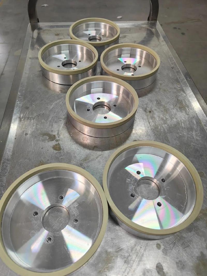
From Drawing Review to Final Grinding
- Drawing & Datum Review
Identify functional faces, datums, flatness, parallelism, thickness, surface finish, material condition, and inspection requirements. - Pre-Machining & Stock Planning
Mill or otherwise machine the overall geometry while leaving controlled grinding stock. Account for section flexibility and access. - Heat Treatment & Stability
Coordinate hardening or stress relief when required. Allow for movement before establishing the finishing setup. - Surface Grinding
Select workholding, dress the wheel, and finish the specified faces. Manage coolant, heat, spark-out, and part orientation through the cycle. - Final Inspection
Verify the required thickness, face geometry, datum relationships, and surface finish using suitable support and measurement methods.
Materials for Surface Grinding
Hardened & Alloy Steels
4140, 4340, C45, bearing steels, and other hardened steel components.
Tool Steels
H13, O1, A2, D2, S7.
Stainless Steels
304, 316, 416, 420, 17-4PH.
Non-Ferrous Metals
Selected aluminum, copper, brass, and titanium alloys where appropriate for the grinding requirement.
High-Temperature Alloys
Selected nickel-based alloys including Inconel 625 and Inconel 718.
Material grade, hardness, stock allowance, geometry, and required surface finish are reviewed together when selecting the grinding approach.
Controlling Flatness, Parallelism & Thickness
A smooth-looking face is not proof of flatness or parallelism. Functional performance depends on the specified geometry, material stability, support condition, and relationship to the drawing datums.
- Thickness
- Flatness
- Parallelism
- Perpendicularity
- Surface finish
- Datum relationships
- Step height
- Mating surface accuracy
Datum Strategy
Relate ground faces to the functional drawing datums rather than treating each surface in isolation.
Thermal Control
Manage grinding heat, coolant delivery, wheel condition, and measurement temperature.
Part Stability
Review residual stress, heat-treatment movement, section thickness, support, and clamping force.
Surface Integrity
Select wheel, dressing, and passes around finish requirements and the risk of burn or metallurgical damage.
Perpendicularity & Step Height
Control adjacent-face relationships, step height, and precision mating surfaces against the drawing datum scheme.
6CNC Inspection & Quality Documentation
Requirement & Typical Inspection Method
- Thickness
- Micrometer / CMM
- Flatness
- CMM / surface plate measurement
- Parallelism
- Micrometer / CMM
- Perpendicularity
- CMM / precision measurement
- Surface Finish
- Surface roughness tester
- Position / Datum Relationships
- CMM
Inspection support, sampling, datum setup, and measurement resolution are selected for the feature and tolerance. Micrometer comparisons for parallelism require an appropriate reference and sampling plan; a single thickness reading does not establish flatness or parallelism.
Typical Inspection Equipment
- Digital micrometers
- Indicators and height gauges
- Surface plate and appropriate supports
- CMM / form measurement as required
- Surface roughness tester
- Gauge blocks
Quality Documentation
- FAI (first article inspection), when specified
- COC (certificate of conformity), when agreed
- Dimensional inspection reports
- Material certificates
- Custom inspection documentation upon request
Inspection methods and required records are agreed with the quotation, using equipment and measurement resolution suited to each feature and tolerance.
Surface Grinding FAQ
What flatness, parallelism, and thickness tolerances can you hold?
Typical thickness tolerance is ±0.005 mm (±0.0002 in). Proposed precision thickness tolerance is down to ±0.003 mm, with flatness and parallelism down to 0.003 mm. These starred limits
What surface finish can surface grinding achieve?
Typical surface finish is Ra 0.2–0.8 μm. The proposed best finish of Ra 0.1 μm remains.
Can you grind hardened steel after heat treatment?
Yes, selected hardened steel faces can be finish-ground after heat treatment. The plan accounts for hardness, distortion, stock allowance, and surface integrity.
Can you grind thin plates or non-magnetic parts?
These parts need appropriate support and workholding. Mechanical or custom fixtures may be used where magnetic holding is unsuitable; thin sections must be assessed for distortion during clamping and release.
Can you machine and grind the complete part?
Yes. Machining, EDM where required, heat treatment, grinding, finishing, and inspection can be coordinated in one project. The quotation defines the included operations.
How do you inspect flatness and parallelism?
Flatness uses a suitable form or CMM measurement plan across the specified face. Parallelism is checked relative to the drawing datum with an appropriate indicator, height measurement, or CMM setup. Support and sampling are defined for the tolerance.
Do you support prototypes and repeat small batches?
Yes. Include the initial quantity and anticipated repeat demand. We plan the workholding, manufacturing route, and inspection scope around the batch.
What should I include with a surface grinding RFQ?
Send a CAD model and PDF drawing with material, hardness, quantity, functional faces, datum scheme, thickness, flatness, parallelism, surface finish, coating requirements, and required inspection records.
Send Us Your Grinding Drawing
Upload your CAD file and controlled drawing with material, hardness, quantity, critical faces, thickness, flatness, parallelism, surface finish, and inspection requirements. Our engineering team will review the manufacturing route before quotation.