
Thin Walls · Distortion Control · Precision Milling · DFM
Thin-Wall CNC Machining for Precision Parts
Thin walls reduce weight and packaging space, but they also make CNC machining less forgiving. 6CNC controls cutting force, workholding pressure, heat and residual stress for stable prototype and small-batch parts.
CNC milling, 5-axis, turning and mill-turn
Aluminum, steel, titanium, copper and plastics
Prototype and small batches from 1–600 parts
CMM and dimensional inspection available
1–600 pcs
Prototype and small-batch focus
4 Processes
Milling, turning, 5-axis and mill-turn
Drawing-Specific
Wall and tolerance engineering review
Documented
Dimensional inspection options
Thin-wall machining services
Control the Part as Its Rigidity Changes
Thin-wall machining is not simply standard CNC milling performed on thinner geometry. A billet may begin as a rigid workpiece, but deep pockets and progressive material removal make the remaining structure increasingly sensitive to cutting forces and fixture pressure.
A flexible wall can deflect away from the cutter, vibrate during finishing, or move after unclamping. Residual stress released from raw material can add further distortion. This is why precision thin wall parts must be reviewed as complete geometries—not judged by wall thickness alone.
At 6CNC, we review wall height, unsupported length, ribs, floors, openings, datums, material condition, tool access and inspection points before choosing workholding and machining sequence. Depending on the part, we use CNC milling services, turning, 5-axis CNC machining or mill-turn machining.
Explore our broader precision CNC machining services.
Thin-Wall Part Photo Reserved
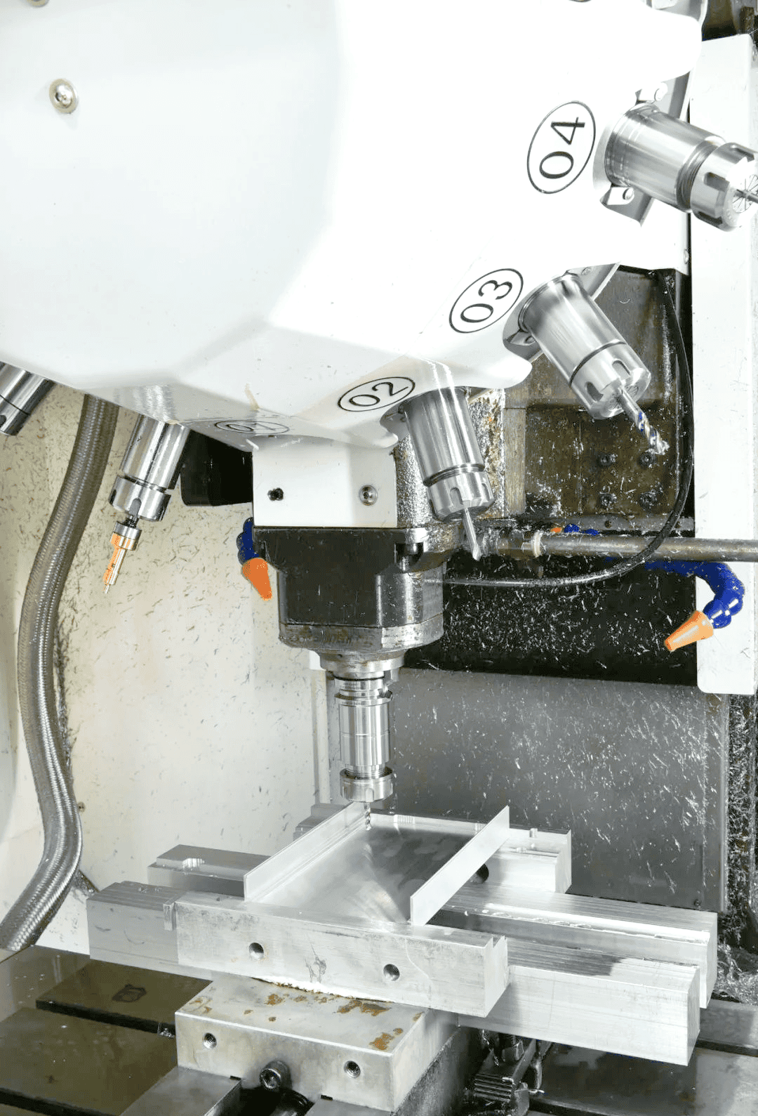
Recommended: real aluminum housing showing thin walls, deep pockets and ribs.
Process control
How We Reduce Thin-Wall Distortion Risk
The process is planned around how stiffness changes during machining—not only the final wall dimension.
STEP 01
Geometry & CTQ Review
We identify unsupported walls, deep pockets, heavy-to-thin transitions, functional datums and critical-to-quality features.
STEP 02
Workholding Strategy
Clamping direction, support locations and fixture pressure are selected to limit restraint-induced movement.
STEP 03
Staged Material Removal
Roughing, stress release and finishing sequences are coordinated to preserve support while the part becomes flexible.
STEP 04
Released-State Inspection
Critical features can be checked after unclamping so inspection reflects the finished part rather than fixture restraint.
Workholding Photo Reserved
Recommended: thin-wall component held during milling, with fixture support clearly visible.
Capability specifications
Thin-Wall Machining Capabilities
Manufacturability cannot be defined by one universal minimum wall number. A short rib-supported wall behaves very differently from a tall unsupported wall of the same thickness.
| Capability | 6CNC Support |
|---|---|
| Machining processes | CNC milling, turning, 5-axis machining and mill-turn |
| Production range | 1–600 pcs |
| Metals | Aluminum, stainless steel, steel, titanium, brass and copper |
| Plastics | Engineering plastics including POM, ABS, nylon and PEEK |
| Part types | Housings, enclosures, brackets, frames, covers and custom structural parts |
| Inspection | CMM, image measurement, surface roughness and dimensional inspection |
| Wall thickness | Evaluated by material, geometry, height, unsupported length and tolerance |
| Drawing formats | 2D drawings and 3D CAD files for quotation and DFM review |
Standard Capability vs. Best-Case Capability
6CNC publishes machining capability down to ±0.002 mm under suitable conditions, but this is not a standard thin-wall tolerance. Actual capability depends on stiffness, feature relationships, setup and measurement method. Send the CAD model and drawing for a project-specific assessment.
Parts and geometries
Parts We Machine With Thin-Wall Features
Thin sections reduce mass, create internal packaging space and preserve room for electronics, optics, bearings, fluid passages and adjacent assemblies.
01
Housings & Enclosures
Electronics, instruments, motors, actuators, optics and sensors with precision interfaces.
02
Frames & Brackets
Lightweight structural components with machined datums, holes and multi-face relationships.
03
Deep-Pocket Parts
Components where long tools, thin floors and unsupported pocket walls increase deflection risk.
04
Covers & Shells
Space-efficient covers with controlled mating edges, cosmetic surfaces and mounting details.
05
Cylindrical Components
Thin-wall sleeves and housings requiring controlled bores, concentricity or roundness.
06
Thermal Components
Heat-management parts with thin fins, pockets and interfaces for compact assemblies.
Best-Fit Geometry
Thin-wall CNC machining is most valuable when a lightweight part still needs precision holes, datums, bearing locations, sealing surfaces, threads or multi-face features. The greatest risk occurs where a section is tall, long, interrupted, poorly supported or connected to a much heavier area.
Unsure Whether Your Wall Geometry Is Practical?
Send the model before finalizing the design. We will identify high-risk sections, tool-access constraints and inspection considerations.
Materials and finishes
Materials for Thin-Wall CNC Machining
Material Group
Aluminum
Common Materials
6061, 6063, 6082, 7075, 2024, 5052
Thin-Wall Considerations
Popular for lightweight housings; stock condition and removal sequence affect stability
Stainless Steel
Common Materials
304, 316, 416, 420, 17-4PH
Thin-Wall Considerations
Higher cutting loads make toolpath and wall support important
Titanium
Common Materials
Grade 2, Grade 5 and project-specific grades
Thin-Wall Considerations
Low stiffness and machining heat require careful planning
Carbon / Alloy Steel
Common Materials
1018, 1045, 4140, 4340 and others
Thin-Wall Considerations
Used when strength or wear performance outweighs weight
Brass / Copper
Common Materials
Project-specific alloys
Thin-Wall Considerations
Used for electrical, thermal and precision functional components
Engineering Plastics
Common Materials
POM, PEEK, PTFE, PC, ABS, nylon and PMMA
Thin-Wall Considerations
Thin features respond to heat and clamping differently from metals
Thin-Walled Aluminum Machining
Thin walled aluminum machining is common for lightweight housings, frames, covers, aerospace parts, robotics structures and electronic enclosures. Aluminum machines efficiently, but removing a large percentage of the billet can release internal stress and leave walls vulnerable to cutting forces.
Surface Finishing
Finishes may include anodizing, chemical conversion coating, plating, passivation, powder coating, painting, polishing and brushing. Specify finishing before machining because coating buildup, masking and cosmetic requirements can affect dimensions and inspection.
Quality and inspection
Inspect Thin-Wall Parts in Their Functional State
Inspection planning matters because measurement restraint can influence a flexible feature. A part may behave differently while clamped than after fixture release.
Critical Dimensions
Walls, bores, hole positions, mating interfaces, datums and sealing surfaces.
Geometric Relationships
Flatness, perpendicularity, parallelism, position, profile and concentricity where specified.
Wall Consistency
Sections where uneven stock removal or distortion could affect assembly or performance.
Surface Condition
Machined surfaces checked where roughness or cosmetic condition is functionally important.
Released Condition
Critical dimensions evaluated after machining restraint is removed where fixture influence is a concern.
Inspection Outputs
Documentation arranged according to drawing, quantity, feature criticality and customer needs.
See our CNC machining quality assurance capabilities.
DFM and cost drivers
What Drives Thin-Wall Machining Cost?
- Wall height and unsupported length
- Wall thickness relative to support
- Deep pockets and long tool overhang
- High material-removal ratio
- Tight dimensional and geometric tolerances
- Dedicated workholding and multiple setups
- Fine surface finish on flexible sections
- Quantity and repeat fixture use
Design recommendations
Design Around Stiffness, Access and Function
- Avoid walls thinner than the application requires
- Reduce excessive unsupported height
- Add ribs or structural transitions where appropriate
- Avoid abrupt heavy-to-thin section changes
- Provide tool access around deep pockets
- Use practical internal corner radii
- Identify critical datums and CTQ dimensions
- Specify cosmetic surfaces separately
- Tell us how the part is constrained in assembly
Manufacturing evidence
What a Thin-Wall Process Plan Should Prove
Supplier capability is more than a minimum-wall claim. A credible plan connects geometry, material, fixturing, sequence and measurement.
Geometry Reviewed
Wall height, length, ribs, pockets and transitions
Restraint Controlled
Support locations, clamping direction and pressure
Sequence Defined
Balanced roughing, stabilization and finishing
Inspection Matched
CTQ features and released-state measurement
Inspection Photo Reserved
Recommended: CMM or optical inspection of a thin-wall component after fixture release.
Representative project profile
Example: Deep-Pocket Aluminum Housing
The profile below illustrates how engineering requirements are translated into a manufacturing plan. It is a representative example, not a claim about a named customer part.
Lightweight CNC Housing With Thin Walls and Machined Interfaces
Material & Geometry
7075 aluminum housing, deep pockets, ribs and unsupported wall sections
Main Risk
Distortion from high material removal, cutting load and fixture restraint
Process Approach
Staged roughing and finishing with support preserved around flexible features
Verification
Critical datums, interfaces and wall-related features checked after release
Case-Part Photo Reserved
Recommended: close-up showing deep pockets, thin walls, ribs and machined interfaces.
Weight- and space-sensitive applications
Thin-Wall CNC Parts Across Critical Industries
Aerospace
Lightweight housings, structural components, brackets and instrument parts.
Robotics
Robot housings, actuator components, sensor mounts and lightweight frames.
Medical Devices
Equipment housings, instrument components and compact precision interfaces.
Semiconductor
Precision covers, housings and tightly packaged equipment structures.
Automation
Sensor housings, machine structures, covers, fixtures and custom components.
Automotive & Energy
Electronic enclosures, thermal parts and lightweight prototype structures.
Upload Your CAD Files for a DFM Review
Get a project-specific review for thin wall CNC machining—from prototype parts to repeat small-batch production. Send your 3D model, 2D drawing, material, quantity, critical tolerances, finish and assembly requirements.
Engineering questions
Thin-Wall CNC Machining FAQ
What is thin-wall CNC machining?
It is a controlled machining approach for flexible sections where cutting force, workholding, heat, material stress and machining sequence can affect final geometry.
What is the minimum wall thickness 6CNC can machine?
There is no universal minimum. Capability depends on material, wall height, unsupported length, ribs, surrounding geometry, tolerances and measurement method. We confirm feasibility after CAD and drawing review.
Which material is best for thin-wall parts?
Aluminum is frequently selected for lightweight structures, but stainless steel, titanium, copper alloys and engineering plastics can also be suitable when the design and machining plan account for their behavior.
How do you reduce distortion?
Depending on geometry, the plan may combine balanced material removal, staged roughing and finishing, controlled toolpaths, practical workholding, intermediate checks and inspection after fixture release.
Can you machine prototypes and repeat batches?
Yes. 6CNC focuses on custom production from 1–600 pieces, including prototypes, first articles and repeat small batches.