6CNC ENGINEERING RESOURCE
Machining tolerance determines how much variation is acceptable. Machining accuracy describes how closely the finished part matches the dimensions, geometry, and positional relationships specified on the drawing.
These two concepts affect almost every machining decision: process selection, setup strategy, finishing operations, inspection requirements, production cost, and whether mating components will assemble and function as intended.
A part can look simple and still be difficult to manufacture if several dimensions, surfaces, or features must be controlled very closely. Understanding where accuracy is actually required helps engineers choose an appropriate machining process without adding unnecessary cost.
This guide is for engineers, product developers, and procurement teams evaluating CNC machining and precision grinding requirements. It explains machining tolerance, dimensional accuracy, form accuracy, positional accuracy, IT tolerance grades, and the processes typically used to achieve different precision levels.
Accuracy fundamentals
What Is Machining Accuracy?
Machining accuracy describes how closely the actual geometry of a machined part matches its specified or theoretically ideal geometry.
In practical machining, accuracy is not limited to whether one dimension is correct. It includes dimensional accuracy, form accuracy, and positional accuracy. A component may meet its nominal diameter while still having unacceptable roundness, flatness, straightness, cylindricity, or feature-to-feature alignment. Evaluating accuracy therefore requires looking at the complete geometry rather than checking only individual dimensions.
What Is Machining Tolerance?
Machining tolerance defines the permitted variation from a specified dimension or geometric requirement.
Example: For a shaft specified as Ø25 +0 / −0.04 mm, the acceptable diameter range is 24.96 mm to 25.00 mm. A finished part inside that range satisfies the dimensional requirement.
As the allowable variation becomes smaller, manufacturing becomes more demanding. The machining process, machine condition, tool condition, workholding, process sequence, and inspection method all become increasingly important. This is why tighter tolerances generally require more process control than ordinary machining.
The Three Main Types of Machining Accuracy
1
Dimensional Accuracy
Describes how closely an actual dimension matches the required dimension. Examples include shaft and hole diameters, thickness, slot width, step height, and distance between features. A correct diameter does not guarantee correct form.
2
Form Accuracy
Describes how closely the actual feature matches its ideal geometric form. Straightness, flatness, roundness, and cylindricity can matter even when the measured size remains within tolerance.
3
Positional Accuracy
Describes one feature relative to a datum or another feature. A correctly sized hole can still cause assembly problems if its axis is in the wrong location.
Drawing review question: Do not ask only what tolerance is required. Identify whether size, shape, position, or a combination of all three must be controlled.
Precision framework
What IT tolerance grades mean
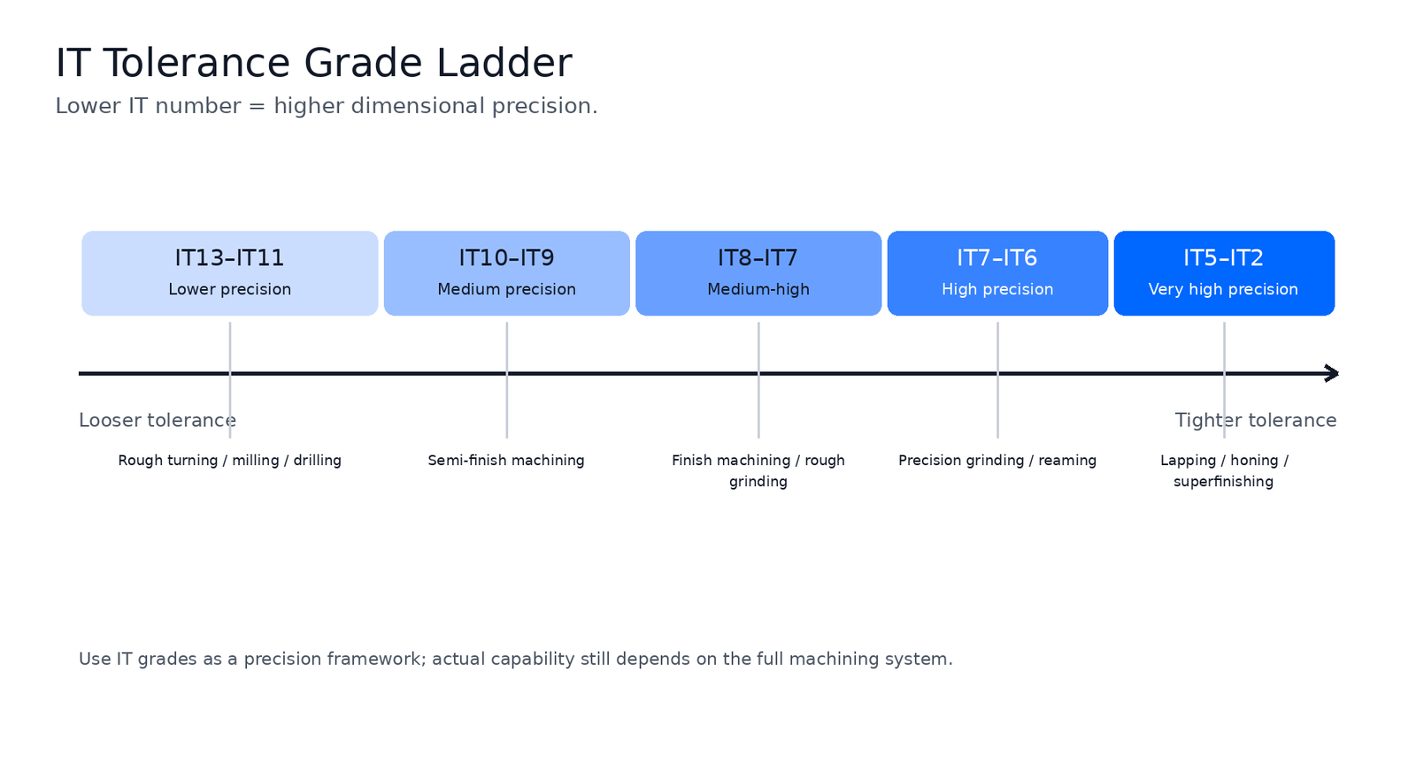
IT grades are internationally recognized tolerance grades used to represent different levels of dimensional precision. A lower IT number means a tighter tolerance grade: IT6 requires greater dimensional precision than IT10.
Common machining work usually falls within the middle IT grades, while very high precision features may require grinding, honing, lapping, or another finishing process. Use IT grades as process-selection guidance rather than a promise that every feature from a particular process will achieve the same result. Actual capability depends on the full machining system, feature size, geometry, material, setup, tooling, and inspection method.
IT grade and surface roughness are related but different
Machining accuracy concerns dimensional, form, and positional error. Surface roughness concerns small-scale irregularities on the machined surface. A process selected for greater dimensional precision often produces a finer surface, but a low Ra value does not automatically prove high dimensional or positional accuracy. When both matter, specify both on the drawing.
Process planning
Typical precision and surface finish by machining stage
The ranges below are reference values for process selection rather than a capability guarantee for every feature. Precision is normally achieved through an appropriate machining sequence. Very tight requirements are rarely approached in the same way as ordinary rough machining.
| Rough machining | IT13–IT11 | Ra 25–12.5 µm | Rough turning, rough boring, rough milling, drilling |
| Semi-finishing | IT10–IT9 | Ra 6.3–3.2 µm | Semi-finish turning, boring, milling, reaming |
| Finishing | IT8–IT7 | Ra 1.6–0.8 µm | Finish turning, finish boring, finish milling, rough grinding |
| Precision finishing | IT7–IT6 | Ra 0.8–0.2 µm | Precision grinding, precision reaming |
| Very high precision | IT5–IT2 | Ra < 0.2 µm | Lapping, honing, superfinishing, polishing |
Rough Machining and Finish Machining Serve Different Purposes
Rough Machining
The primary purpose of rough machining is to remove material efficiently. At this stage, the process is focused on removing excess stock, establishing the basic geometry, and preparing the part for later operations.
The final dimensional and surface requirements are not normally achieved during the first roughing operation. Material is intentionally left for subsequent machining.
Semi-Finishing
Semi-finishing brings the part closer to its final geometry. It reduces the amount of material that must be removed during finishing and creates a more controlled condition for the final operation.
For parts requiring tighter tolerance, this intermediate stage can help separate heavy stock removal from the operation responsible for final accuracy.
Finish Machining
Finish machining is used to achieve the required final dimensions and surface condition. Depending on the tolerance requirement, the operation may involve finish turning, finish milling, finish boring, reaming, or grinding.
If the required tolerance is beyond the practical range of conventional finish machining, an additional precision finishing process may be required.
Higher accuracy
When Is Grinding Used for Higher Accuracy?
Grinding is commonly used when higher dimensional precision and lower surface roughness are required than can economically be achieved by ordinary cutting operations.
Typical applications include precision shafts, bearing surfaces, cylindrical fits, precision flat surfaces, hardened components, and features requiring tight final size control.
A common process route for a precision external cylindrical surface may progress from rough turning to semi-finish turning, finish turning, and then grinding. For still higher requirements, the sequence may continue with more precise grinding or superfinishing operations.
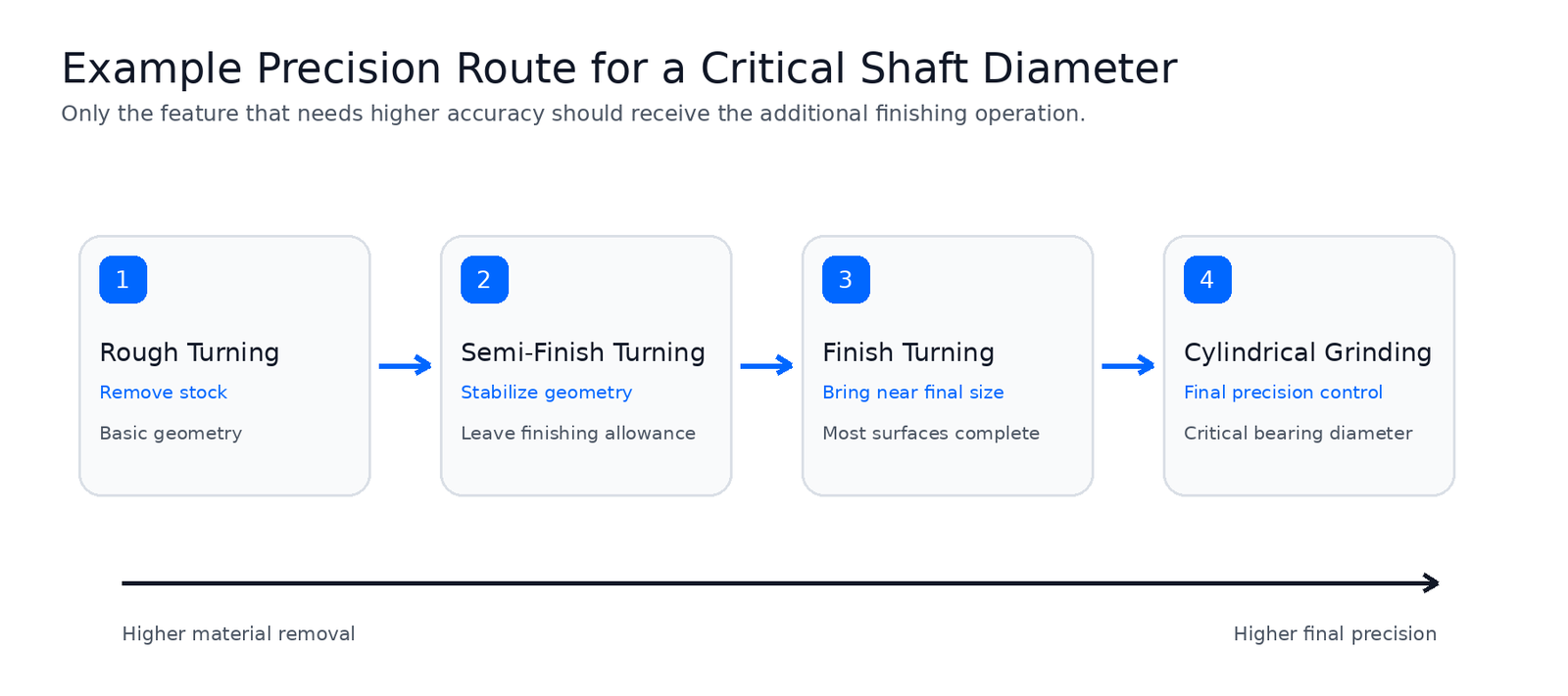
Process-selection principle: Leave appropriate material for the final precision operation instead of trying to reach the finished dimension too early.
Process selection
Choosing a Machining Process Based on Required Accuracy
For Relatively Loose Dimensions
A rough machining operation may already provide sufficient accuracy. Examples include rough turning, rough milling, and drilling. Adding a precision finishing process provides little value when the drawing does not require it.
For Medium-Precision Dimensions
Semi-finish or finish machining may be sufficient. Processes can include finish turning, finish milling, finish boring, and reaming. These operations are widely used when the required dimensional accuracy is tighter than rough machining but does not justify precision grinding.
For High-Precision Dimensions
Grinding or another precision finishing process may be required. The machining route should leave appropriate material for the final precision operation instead of attempting to achieve the finished dimension too early.
Tolerance and Process Selection
When reviewing a drawing for manufacturability, the required accuracy should be considered together with the planned process.
| Required accuracy | Typical process direction |
|---|---|
| Loose tolerance | Rough or conventional machining may be sufficient |
| Moderate tolerance | Semi-finish or finish machining |
| Tight tolerance | Controlled finishing operation |
| Very tight tolerance | Grinding or another precision finishing process |
The tighter the requirement becomes, the more important it is to control the complete process rather than only the final machine setting.
Functional tolerancing
Do Not Specify Every Feature to the Same Precision
One of the most important decisions in part design is determining which features actually require tight control. Not every dimension on a component performs the same function.
Some dimensions may control bearing fits, shaft alignment, sealing surfaces, assembly location, motion, or feature-to-feature alignment. Other dimensions may only define clearance or non-critical geometry.
Applying very tight tolerances to every dimension can make machining more complicated without improving the function of the part. A more effective drawing distinguishes between critical and non-critical characteristics.
Accuracy Should Be Considered Feature by Feature
A part should not be described only as a ±0.01 mm part or a high-precision part. Different features perform different functions and can require different controls.
- A bearing diameter may need tight dimensional accuracy.
- A mounting face may depend on flatness.
- A hole pattern may depend primarily on positional accuracy.
- A cosmetic surface may need a specific finish while allowing a wider dimensional tolerance.
The machining plan should reflect these different requirements. That is often more effective than applying one tolerance value to the entire component.
Complete process control
Why Final Accuracy Depends on More Than the Machine
Machining accuracy is the result of the complete manufacturing process. Even when a machine is capable of precise movement, the finished part still depends on whether the required dimensions, shapes, and positional relationships are correctly maintained throughout production.
The machining method must therefore be selected according to the feature being produced and the accuracy required. For high-precision work, rough material removal and final precision machining are often separated into different stages so that the final operation is responsible for bringing the critical feature to specification.
Machine capability is only one factor. Tool wear, workholding stability, thermal effects, thin walls, deep pockets, long unsupported features, and material movement can all change the final result.
Practical examples
Practical Example: Precision Shaft
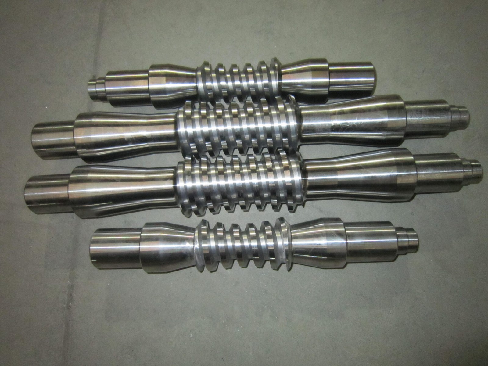
Consider a shaft with several outside diameters. Some sections may simply provide clearance and require ordinary turning. Another diameter may locate a bearing and require substantially tighter size control.
The process route could use rough turning to create the basic shaft geometry, followed by semi-finish and finish turning on most external surfaces, while the critical bearing diameter receives final cylindrical grinding to achieve the required precision.
This is more practical than grinding the entire component simply because one feature requires higher accuracy.
Practical Example: Precision Hole
The same principle applies to holes. A basic clearance hole may only require drilling. A more accurate hole may require drilling followed by reaming, or rough boring followed by finish boring.
If the required precision becomes substantially tighter, additional precision finishing may be necessary. The correct process depends on the final tolerance rather than the fact that the feature is simply described as a hole.
For assemblies with several mating parts, review tolerance stack-up as a system. A dimension that is acceptable by itself can still create risk when variation accumulates across plates, pins, shafts, or other components.
Cost and manufacturability
How machining tolerance affects cost
As tolerance becomes tighter, the machining route may require additional operations. A feature that can be produced directly by turning or milling is generally simpler than one requiring rough machining, semi-finishing, finish machining, and grinding.
For this reason, tolerance should reflect the functional requirement of the component. The goal is not to specify the smallest possible tolerance. The goal is to specify the tolerance that allows the part to function correctly and consistently.
Tighter limits can require lighter cuts, more stable workholding, additional offsets, controlled inspection temperature, and more capable measuring equipment. Yield risk can also rise because tool wear, deflection, and material movement consume a larger share of the available tolerance.
What Information Should Be Reviewed Before Machining?
When a drawing contains precision features, the manufacturing review should identify:
- Critical dimensions and dimensional limits
- Form requirements such as flatness, roundness, or cylindricity
- Positional relationships and datum references
- Surface-finish requirements
- Features likely to need a separate finishing operation
This makes it possible to determine which surfaces can be produced by standard CNC machining and which may need precision grinding or another finishing process.
Verification
Machining Tolerance and Inspection
Inspection should verify the same characteristics that the drawing controls. If the requirement concerns dimensional accuracy, the finished dimension must be checked. If the requirement concerns form, the relevant geometric characteristic must be verified. If the requirement concerns position, the relationship between the feature and its datum must be evaluated.
This is why reading the drawing correctly comes before selecting an inspection method. The inspection plan should follow the engineering requirement rather than treating every feature as a simple linear dimension.
The inspection method must have enough resolution and repeatability for the specified tolerance. Depending on the characteristic, that may mean a bore gauge, height gauge, roundness instrument, or coordinate measuring machine rather than a general caliper check.
Machining Accuracy at a Glance
- Dimensional accuracy: controls actual feature size.
- Form accuracy: controls deviation from ideal shape.
- Positional accuracy: controls the relationship to a datum or another feature.
- IT grade: classifies dimensional precision.
- Surface roughness: describes microscopic surface texture and is separate from dimensional accuracy.
- Machining process: should be selected for the accuracy and feature that actually require control.
Common questions
Frequently asked questions
What is machining tolerance?
Machining tolerance is the permitted variation allowed for a specified dimension or geometric requirement. A finished feature does not need to equal the nominal value perfectly, but it must remain within the allowable limits shown on the drawing.
What is the difference between tolerance and accuracy?
Tolerance defines the acceptable variation. Accuracy describes how closely the actual machined part matches the specified geometry. A machining process must be capable of producing results consistently within the required tolerance.
What are the three main types of machining accuracy?
Machining accuracy can be divided into dimensional accuracy, form accuracy, and positional accuracy. All three can affect whether a component fits, assembles, and performs correctly.
Does a smaller IT grade number mean higher precision?
Yes. A lower IT grade represents a higher level of dimensional precision. For example, IT6 represents tighter dimensional control than IT10.
What IT grades are commonly associated with CNC machining?
Different processes cover different ranges. Rough machining is typically associated with looser IT grades, while finish machining provides greater precision. Grinding and other precision finishing processes are commonly used when tighter IT grades are required.
Is surface roughness the same as machining tolerance?
No. Surface roughness describes microscopic surface texture. Machining tolerance controls allowable variation in size or geometry. A part can have a smooth surface without having high dimensional accuracy.
When should grinding be used?
Grinding is commonly considered when the required dimensional precision or surface finish exceeds what ordinary turning, milling, or boring can practically provide. It is frequently used as a final finishing operation on precision cylindrical and flat surfaces.
Does every dimension need a tight tolerance?
No. Tolerance should be based on the function of the feature. Critical fits, alignment features, bearing surfaces, and other functional characteristics may require close control, while non-critical geometry can often use wider tolerances.
6CNC ENGINEERING SUPPORT
Need help reviewing a tolerance requirement?
If your part includes tight fits, precision bores, bearing surfaces, critical datums, or demanding surface-finish requirements, send the engineering package to 6CNC for review.
What to Send
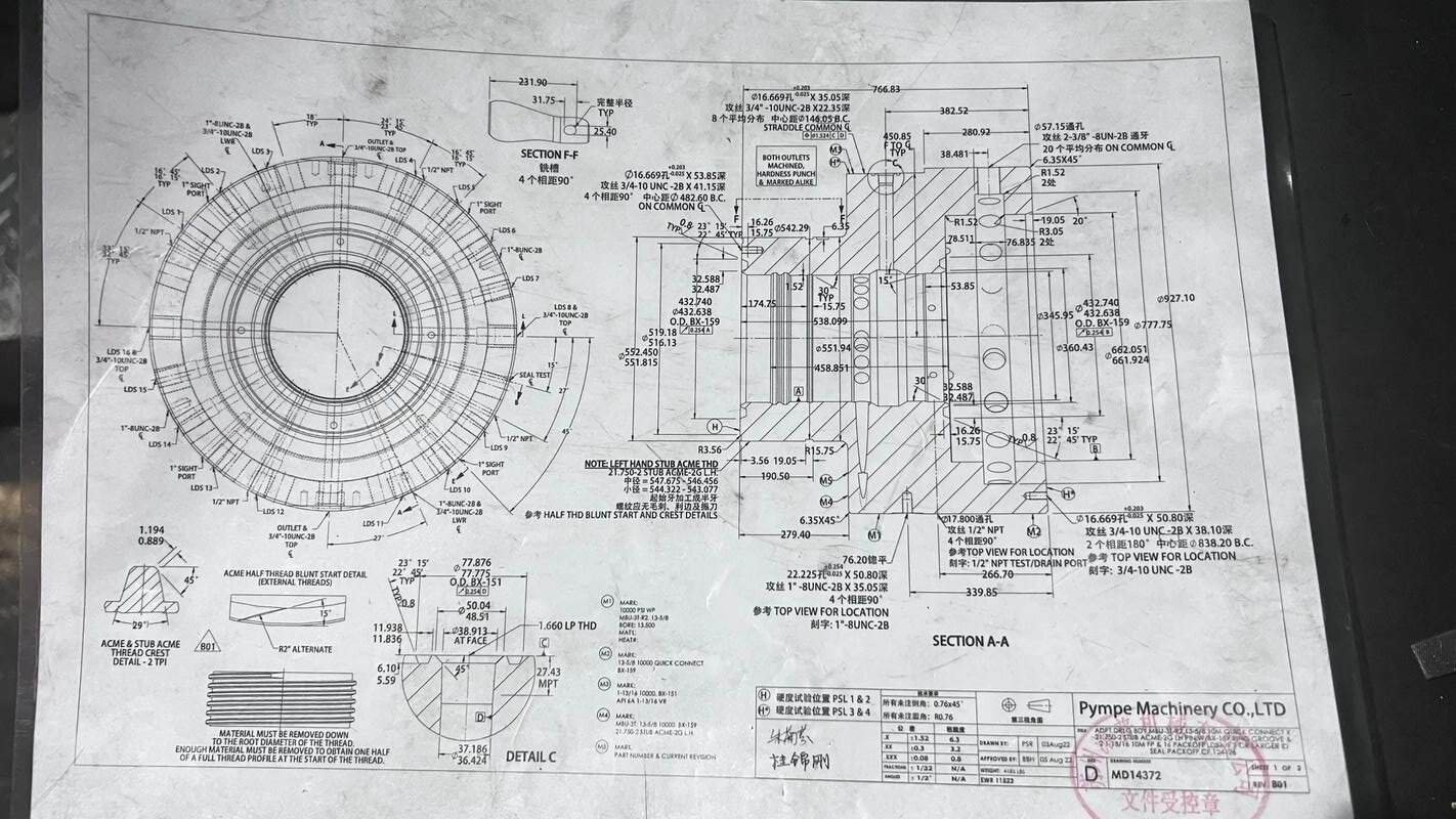
- 2D Drawing: Include tolerances, datums, GD&T, and surface-finish callouts.
- 3D CAD Model: STEP or another neutral CAD format is preferred for geometry review.
- Critical Requirements: Identify fits, bearing surfaces, sealing surfaces, and dimensions that drive function.
We can review which features are suitable for standard CNC machining and which may require additional finishing such as precision grinding.